Project Overview
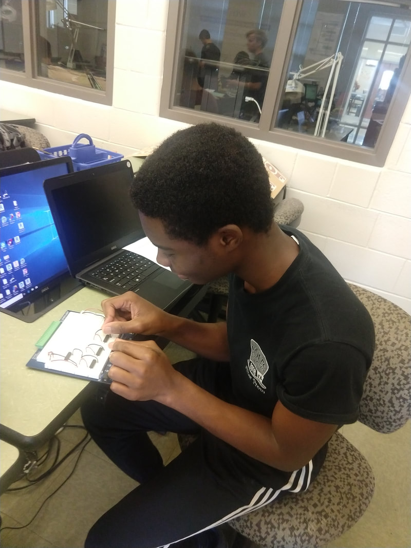
This is the Date Of Birth project where we have to display our dates of birth using 7 segment displays. The circuit will either turn the segment on or off, displaying the month day and year of our birth. Some of the constraints includes, using a common cathode seven segment display, having to use current limiting resistors, and using k-mapping to find the simplified logic expression for each of the segments. This report will explain the steps i took to complete this project.
Truth Table
This is my truth table. Its purpose is to help me find the values that I need to make the circuit work.
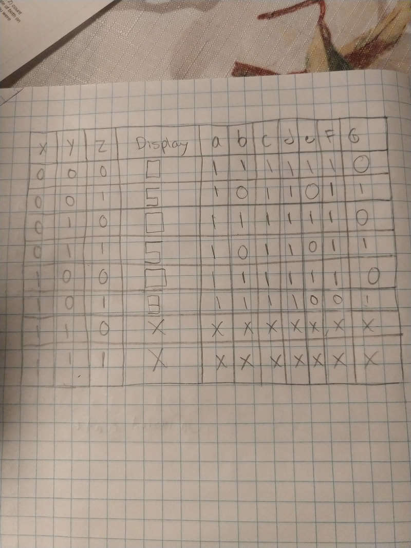
This table allows me to first, going horizontally, write down the values I need that will turn on a certain segment, showing the number I need. Then after that, going vertically, you input the values of each column into a k-map table for each letter or segment. We have a through g columns because that is representative of the segments in the seven segment display. x in this display is a don't care condition, that means that it doesn't really matter what value it is because we don't need the display to display anything at that time.
K-mapping and Simplified Logic
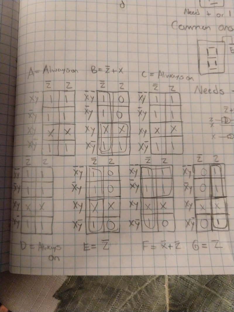
K-mapping is inserting the values found from the truth table, into a table with however many spaces as the number of values. After that you group all the 1's in the biggest groups possible by 2's, 4's, 8's and 16's. These expressions are is sum of product form. I arrived at these expressions by grouping up the ones and canceling out the opposite variables on the sides of the table. I am using K-mapping instead of Boolean algebra because it is way easier and more simple to work with. I have so many expressions because it will allow me to use only 3 switches to display my birth date and also it will turn off and on the segments that are needed to show my birth date.
MultiSim
This is the circuit that I have made on Multisim, the computer circuit modeling program. It helps to make sure your circuit works before you build it.
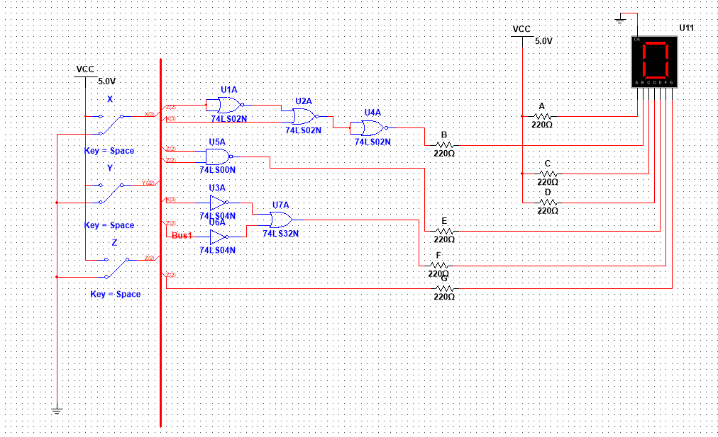
This circuit is in bus form. In order to recreate this circuit I used 3 - 74LS02 gates, 1 - 74LS00 gate, 2 - 74LS04 gates, and 1 - 74LS32 gate. Based off that I would need, 1 - 74LS02, 1 - 74LS00, 1 -74LS04, 1 - 74LS32 chip. We use NAND and NOR gates because they can be easier and less costly to implement into a circuit as you use the same chip for the whole circuit and generally, less gates are used. When I converted my circuit to NOR chips it actually contained more gates than the AOI implementation. The circuit would use the same amount of chips though because of the type of circuit it is. The type of circuit implementation is important because in the wide scale production of the product, it can save you a lot of money depending on the way you choose to make the circuit. A seven segment display works by taking a value, either 1 for a cathode and 0 for a anode, and lighting up the segment that value was input to. A common cathode is a SSD that is grounded so it needs values of 1 to work. A common anode is a SSD that is connected to voltage so it needs a ground or 0 to work. We are using a common cathode because our switches output values of 1 when turned on. The purpose of a resistor in the circuit is to limit the voltage so the SSD will not short circuit or blow. The common vale of the resistor 220 ohms.
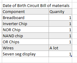
Bill of Materials
This is the list of materials used in the bread boarding section of this project.
Bread-boarding
|
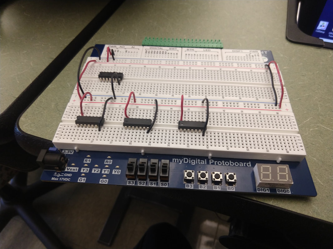
This is the start of the project after hooking up the simple connections.
|
|
|
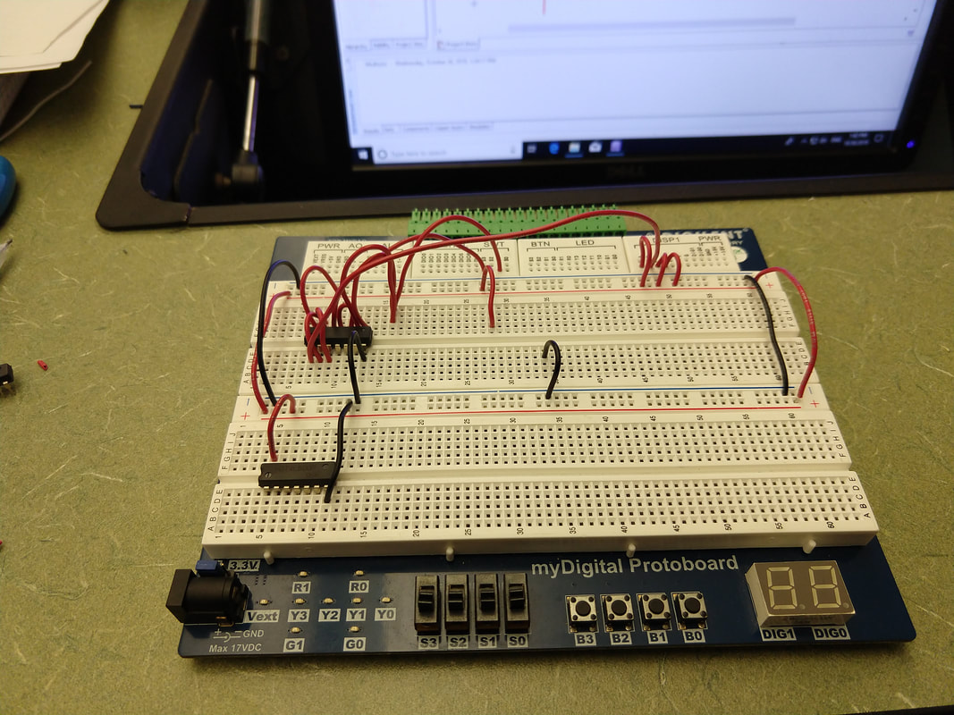
This is my circuit after getting 2 gates done.
|
|
|
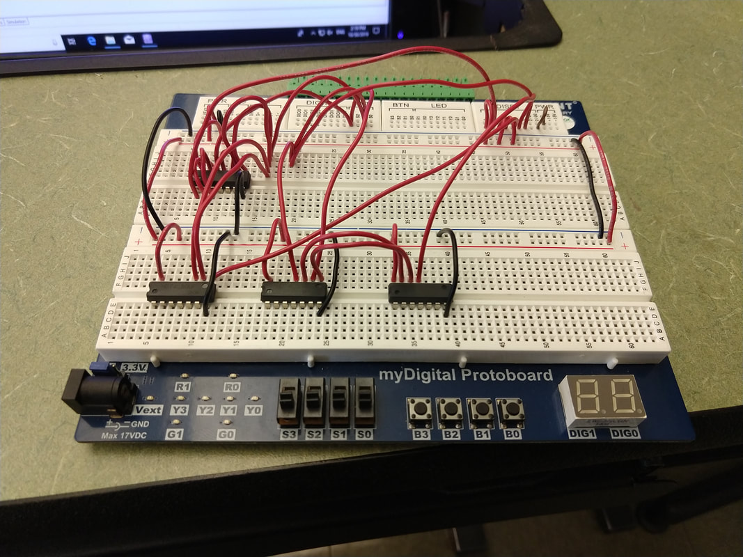
This is my completed circuit and it works perfectly!
|
|
This bread boarding experience was probably the easiest part of this project. My circuit was very simple so it didnt take long to make. I didnt have many problems with is as it worked the first time. I did learn new ways to lay out the chips and move the pins so that there would be no confusion or mistakes.
Conclusion
In this project I learned a lot of new things. These things included learning how to bread-board, use K-maps and use truth tables better. Next time when I do this I would take my time when figuring out the truth table and the expressions because I had made a small mistake and that took a long time to fix after I had already built the circuit. Some unanswered questions I have are what could be done to the circuit and or bread board to make my birth date display on a cycle so I only have to press a button.
Extra Credit
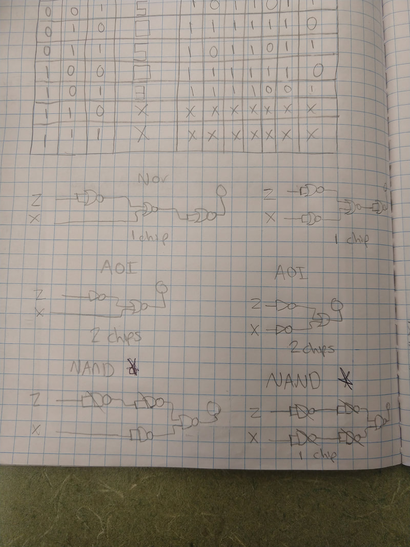
The simplest circuit I can make is a circuit made out of NAND gates. This circuit ties for least amount of chips with NOR gates, but if I use NAND I will use less gates than the NOR implementation.
