Beginning
In this project, my partner Daniel and I, built a copier jam model and designed a circuit for it on Multisim.


Circuits
It was a bit complicated to read the exterior wiring diagram but, once we took a second look we were able to use it to build our circuit. The concept of adding the flip flop into our combination logic design was not hard but, when trying to make it physically on the board, we had many problems. All of the problems did have to do with the condition of the board and the chips though.
Resistors: We had resistors to provide a path of least resistance in the circuit
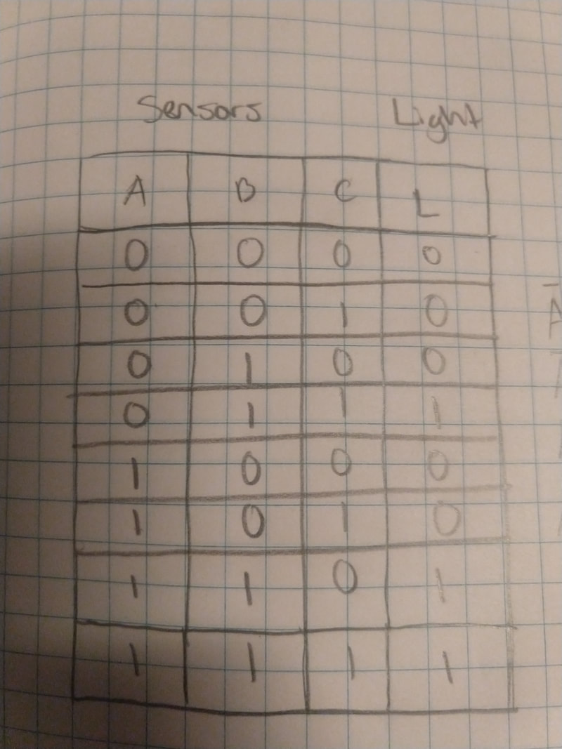
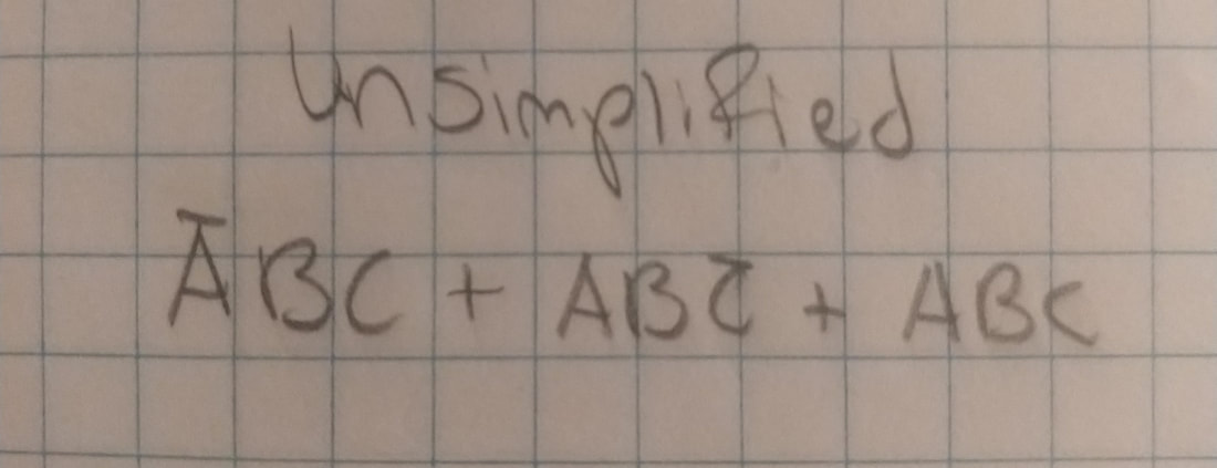
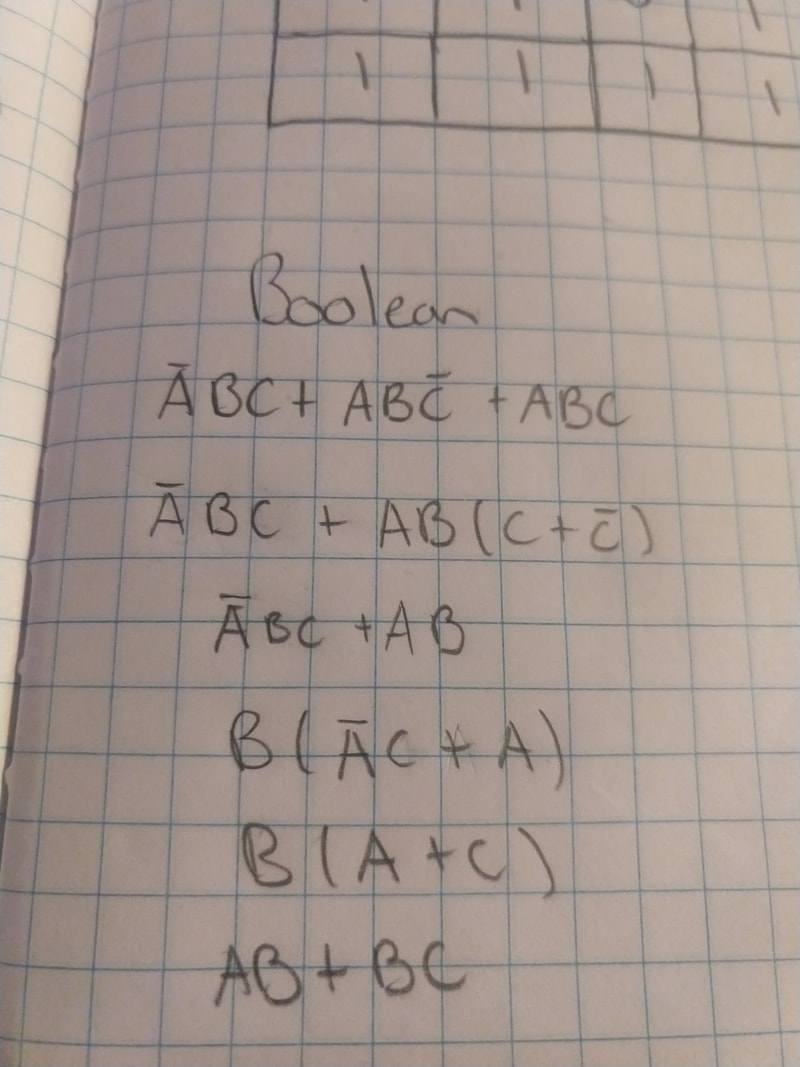
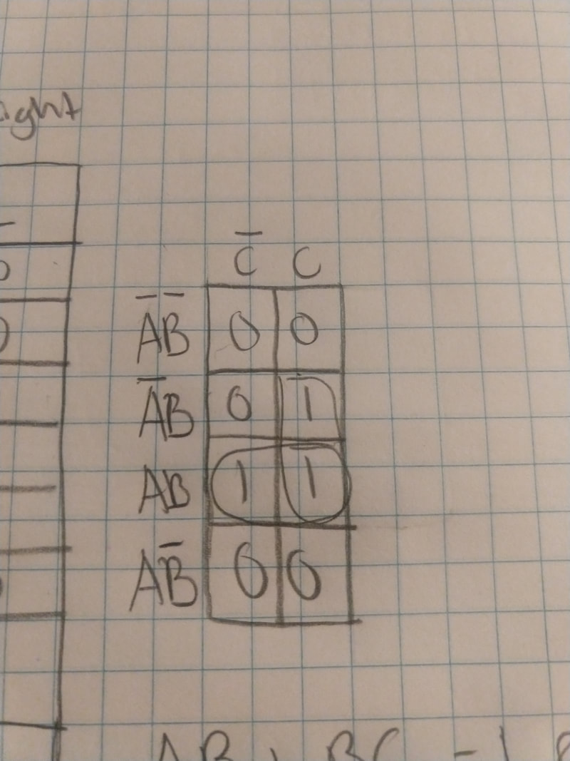
Combinational logic circuit: This makes the conditions for the sensors in the circuit to detect, setting off the light or the buzzer
Flip Flop: This allow us to clear the buzzer and turn it off after it has been activated
LED and Buzzer: The LED goes off and the buzzer stays on because the flip flop provides the speaker with an out put of 1 until clear is activated, killing the signal.
Relevant: Our circuit demonstration may look a bit weird because of the faulty board, but I assure you it works!
Conclusion
This project was very different from other projects we have done. Here are some ways this project is different:
- The representation of the project, being a copier machine jam, is more realistic than our other projects
- We implemented J K flip flops into our circuit
- We also built and used the FT construction as our inputs
